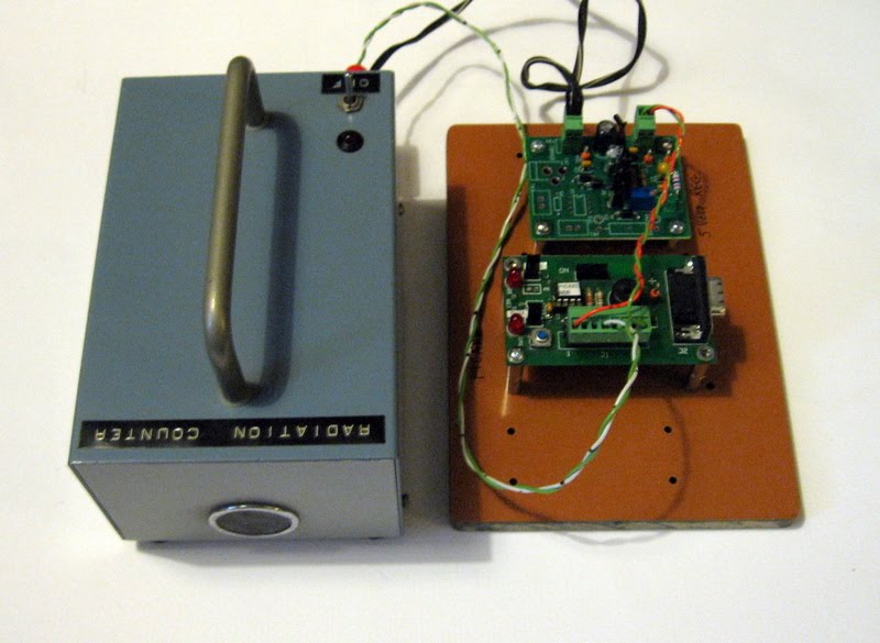
Saturday, November 28, 2009

Zi8 on button glows when off


I noticed that the power button on the side of the Kodak Zi8 glows when off. Its just a tiny glow, but you can see it in a fully dark room. At first I thought it was side illumination leaking into the case, but not so in a fully darken room. Could this be wasting power as it sits in the "off" position? What the purpose of allowing the led to light? Could I have a leaky transistor lighting up the led?

Sunday, August 2, 2009

16F88 3-digit voltmeter


I wanted to make a simple 3 digit voltmeter for mounting inside a power supply for troubleshooting purposes. Scouting around the internet, I couldn't find anything complete enough to make a meter. So I decided to make my own using Pic Pro basic to program a 16F88 PIC. Micro Engineering Labs has a good tutorial on how to interface a 4 digit led display to a pic. The tutorial was helpful enough that I was able to fashion a circuit and program into a usable meter. Then it dawned on me that the circuit could become an event counter by changing the input stage and program. The event counter uses a 16F628A or 16F88, since both pics have the same I/O pinout.

The circuit is also compatible with a frequency counter I found on the net. This circuit uses a 16F628. Use code "COUNTER3.HEX" for common anode display found at that site. This site got me started in making a multipurpose board.

Below I included links to my programs and schematic for anyone else to make there own. You can use the programs and circuit freely, just don't make money with it.


PBP Basic Program as 100V meter.
Hex file for 16F88 PIC
Schematic in PDF

PBP Basic Program as event counter.
Hex file for 16F628A
Hex file for 16F88

Sunday, June 28, 2009

Midi to Relay Controller


I've been looking for a schematic and code for a Midi to relay decoder. I finally found one that actually works well. This circuit will work with sequencer software and commands relays or solenoids with Midi. I plan to make a robot drummer controlled by sequencer software. The decoder required turning on several solenoids at the same time with precision, following notes from a drum sequencer. The circuit and code is free and so is the drum sequencer software (DrumFlow 1.7) that I'm using to test the code. My video on youtube show several outputs turning on at the same time. Just what I wanted. You don't need to wire up all 32 outputs, just use what you need and eliminate the other driver ICs. With just a 16f84 PIC and two other ICs you can drive eight drummer solenoids. Thats enough for a hell of a drummer.

Wednesday, June 10, 2009

Hard Drive Afterlife


So your aging hard drive can't hold its data any longer and you replaced it with a new one. Instead of letting it die by the hands of the recycling undertaker, you force it into a new life as a musical noise maker. A dying hard drive makes all kinds of grunts and groans as it starts up. The sounds it makes can be musical and percussive.

This project uses a homemade PIC midi interface to allow sequencer software (Anvil Studio free) to turn on and off eight hard drives. Midi signals are serially transmitted by the sequencer software as sets of 3 bytes at 31,250 baud. A PIC 16F877 has been programmed to receive these bytes to turn on and off solid state relays. Each hard drive needs 5 volts and 12 volts to run. Two SSRs are used to turn on and off the hard drive. I tried leaving on just the 12 volts, then switch on 5v to start the drive up. This worked well for awhile until one smoked up. So I use two SSRs to switch on both 5 volts and 12 volts at the same time. A modified PC power supply is used to supply power. A tuner pickup and computer soundcard amplifies the sounds, making the point that something went horribly went wrong with those drives.

The project is for testing the idea of making a larger kinetic/musical artbot "tree" consisting of 24 hard drives. Each hard drive will be mounted as a branch extending from a central trunk in a circular spiral.

This is what happens when you don't throw away broken stuff, you make something cool out of it.

Schematic here.
Pic Pro Basic Code here.
HEX code here.

You can download an mp3 file of the sounds here.
Email me (see my webpage) or leave a comment to check for updates as the code is evolving.

Sunday, February 8, 2009

Fix your Garden Light

I bought several cheap Hampton Bay garden lights at Home Depot a few years ago. Part number 498-959. The clear plastic diffuser that supports the electronics has become brittle and fell apart. I suspect its the UV from the sun and has broken down the chains of molecules of the plastic. Instead of throwing them away, I discovered they will fit on top of a Ball canning jar with little effort. First remove the four Philip head screws that hold the two halves of the solar head.


There are four holes already in the solar head. Use two of them with 6-32 machine screws and nuts to attach the canning jar lid. You can see the screw heads in the photo below just inside the lid's rim. In the photo above, you can see the nuts of these two screws

Now the glass won't fall apart like the plastic in the sun. You may need a little caulk around the edges to seal out water. I intend to place mine in my window to light up at night, so theres no water proofing required. If you want more info about the schematic inside, go here to my webpage. I also wrote about the plastic falling apart problem in this 2007 blog.

Monday, December 1, 2008

USB Logger using a Vdrive2


I built a simple Data logger using a Vinculum Vdrive2. The logger records two sources of voltages within 0 to 5 volts. An 8 bit entry every second is recorded in a USB stick as a .csv file, suitable for use in Excel.

When I first got my Vdrive2 module, I built an RS232 interface to allow sending commands and viewing the responses with Hyperterm. My schematic of the interface can be found here.

You can update the flash ROM on the module by going to FTDI's website and downloading a FTD file to the memory stick. By changing the name to ftrfb.ftd, the Vdrive2 will detect the file and upgrade itself when powered up. Once this is done, remove the file from the stick before starting again. Otherwise it will try re-flashing the ROM again. When I got the module, it had a pretty old version in it, version 2.08.

Each entry into the USB stick is as follows:

A time stamped number of YYMMDDHHMM,ADC value1,ADC value 2,cr

2 hours worth or 7200 entries are placed in a file with the following date stamp.

YYMMDDHH.csv

How the logger works.

A debug port from the logger allows one to follow the operation in realtime with a PC running Hyperterminal.

The logger uses a DS1307 real time clock for date information. To set the date, a small file is placed on the USB stick. You can use notepad to make this little file. Name it "date.txt"

Using notepad, format the date as follows:

yy:mm:dd:hh:mm

As an example, the time is 2008 on November 24th at 2 pm. 24 hour mode is used. The sequence would be:

08:11:24:14:00

When starting up, the little file is read and the date is set. Then the file is renamed to "ndate.txt" to prevent changing the time again. To reset the time, change the file to a new date and rename back to "date.txt". This makes setting the RTC easy.

To prevent loss of data while a file is open, a backup supply is turned on. An opto coupler is used to detect when to start and stop logging. Power to the opto comes from the main source of power. When the power drops off, the file is first closed and backup power is disconnected when done.

My first prototype was built on perfboard with plans to make PC boards in the future (if enough interest is generated). The pic microcontroller is a 16F688 and programmed using Pic Pro Basic. I used Microcode Studio as an IDE and programmed the Pic using the PICkit 1. To do ICSP, I made a little adaptor to bring out the connections from the PICkit 1 to the project. USB stick used with this project was a Kingston Data Traveler DTI/256.

I'm not the best in writing clean programs, but it works. Any suggestion on improvement is welcomed. One idea for improvement is to start getting it to delete the oldest files when the stick gets full. That would require making the memory into a circular buffer. Just haven't figured the file management scheme yet.

Schematic: Vdrive2 Project

Code (8 bit version):
Program "1_PerSec.bas"

HEX file "1_PERSEC.HEX"

date.txt

Typical file "08120117.csv"

10 bit version

program

hex file

Tuesday, April 29, 2008

Joule Thief Artbots

BatteryBot

A popular circuit for electronic hobbyists called a "Joule Thief" has been making the rounds on the Internet.
When your batteries go dead, there is still energy or "joules" still left in that battery. Instead of simply tossing it out to get recycled, why not squeeze out the remaning joules of life to do something useful.

With the Joule Thief circuit you can light a white led till the battery is down to .2 volts. Use it for a night light, it will run for days. Then, when it is good and dead, give it to the trash collector to get recycled.

2/10 volt and the led is still on!

The circuit consists of a ferrite core with a double winding, a transistor, resistor, led and the "dead" battery for power. Thats all there is. Sure you can put the parts on a perf board and make it work. I wanted more, so I built some artbots with the parts.

Ferrite

Ferrite uses a vintage germanium transistor to be able to run at very low voltages. Like all the way down to .2 volts.


Germanium

Germanium also uses a vintage (1966) germanium transistor. This one is from General Electric. "Ge" is also the elemental name of germanium on the Periodic Table of Elements!

Here is a good modification you can do. Change the 1k resistor to something around 2.2k to 10k and place a CDS light sensitive resistor between the transistor base and emitter (or use a trimmer). This mod will make the circuit light sensitive and cause the circuit to shut down during the day. When its dark , the white led will light. Now how about that for a proper night light!

So go ahead and google "joule thief" and see what you can find, then make your own artbot.